Dear all,
I am still struggling with PIO on both the Raspberry Pi Pico (RP2040) and Pico 2W (RP2350) while preparing Chapter 6 of my Ada on the Raspberry Pi Pico tutorial. I would be very grateful for any insight from those who have successfully driven PIO state machines from Ada.
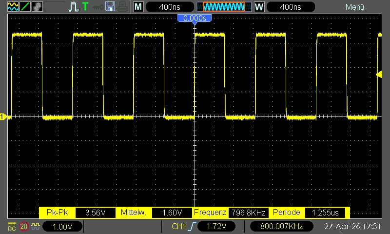
The goal of the minimal test is the simplest possible square wave (no DMA, no side-set, no structured data, just two set pins instructions). The expectation is an 800 kHz 50 % duty-cycle signal on GP2 (physical pin 4).
with RP.Device;
with RP.GPIO;
with RP.PIO;
with RP.Clock;
with Pico.UART_IO;

--  Generate a clean 800 kHz square wave on GP2 using PIO Tested on both Pico and Pico 2W (RP2040 / RP2350) This scetch
--  is meand to be used with an oscilloscope to verify the timing of the PIO program. You should see a perfect 1.25 µs
--  period, 50% duty cycle square wave on GP2 (physical pin 4). Optionally use CoolTerm or similar to monitor the debug
--  output.
procedure Square_Wave is
   --  The squarewave program above (you can also load it from .pio file via pioasm)
   --!pp off
   Squarewave_Program : constant RP.PIO.Program := [
                        --  .program squarewave
                        --  .wrap_target
       0 => 16#6001#,   --  set pins, 1 [0]     ; high for 1 cycle + delay
       1 => 16#6000#    --  set pins, 0 [0]     ; low  for 1 cycle + delay
                        --  .wrap
   ];
   --!pp on

   --  Choose any free GPIO. GP2 is convenient (pin 4).
   Pin          : RP.GPIO.GPIO_Point renames Pico.GP2;
   PIO          : RP.PIO.PIO_Device renames RP.Device.PIO_0;
   ASM_Offset   : constant RP.PIO.PIO_Address := 0;
   Freq         : constant                    := 800_000;
   SM           : constant RP.PIO.PIO_SM      := 0;
   Config       : RP.PIO.PIO_SM_Config        := RP.PIO.Default_SM_Config;
   System_Clock : constant RP.Hertz           := RP.Clock.Frequency (RP.Clock.SYS);
begin
   Pico.UART_IO.Initialise;
   Pico.UART_IO.Put_Line ("+ Square_Wave");
   Pico.UART_IO.Put_Line ("=== 800 kHz PIO Square Wave Test ===");
   Pico.UART_IO.Put_Line ("Scope on GP2 (physical pin 4)");

   --  Make sure system clock is 125 MHz (default on both Pico and Pico 2W)
   if System_Clock in 125_000_000 | 150_000_000 then
      Pico.UART_IO.Put_Line
         ("Warning: SYS clock is " & System_Clock'Image &
          " not 125 MHz (Pico) / 150 MHz (Pico 2W). Timing will be off!");
   end if;

   --  Configure the GPIO for PIO control
   Pin.Configure (RP.GPIO.Output, RP.GPIO.Pull_Up, PIO.GPIO_Function);

   PIO.Load (Prog => Squarewave_Program, Offset => ASM_Offset);
   PIO.Set_Pin_Direction (SM, Pin.Pin, RP.PIO.Output);

   Config.Set_Out_Pins (Pin.Pin, 1);
   Config.Set_Wrap (ASM_Offset + Squarewave_Program'First, ASM_Offset + Squarewave_Program'Last);
   Config.Set_Clock_Frequency (Freq);

   PIO.SM_Initialize (SM, ASM_Offset, Config);
   PIO.Set_Enabled (SM, True);

   --  Start the state machine
   PIO.Enable;

   Pico.UART_IO.Put_Line ("Square wave running on GP2 at 800 kHz.");
   Pico.UART_IO.Put_Line ("You should see a perfect 1.25 µs period, 50% duty cycle.");

   --  Keep the main task alive
   loop
      Pico.UART_IO.Put_Line ("Still running... Check your scope! ... Stop with debug console.");
      delay 1.0;
   end loop;
end Square_Wave;
Observed behaviour (identical on both Pico and Pico 2W, multiple GPIO pins, single-stepped with debugger):
- The pin sits at 0 V after reset.
- During initialisation it jumps to ~3.27 V and stays there – a perfect flat line on the oscilloscope.
- No toggling occurs, even though the state machine reports as enabled and the PIO block is enabled.
- The same code path was used with the original
ws2812_demofrom Jeremy Grosser (with and without DMA) – same result: static high after one transition.
I have verified:
- The program loads correctly (offset 0, two instructions).
- Wrap is set to the two-instruction block.
Set_Pin_DirectionandSet_Out_Pinsare called.- The GPIO function is correctly set to PIO.
- System clock is the expected 125 MHz / 150 MHz.
What I am unsure about is whether the square-wave program itself is correct for the Ada binding. In C SDK examples the equivalent often includes an explicit set pindirs, 1 inside the PIO program or uses sm_config_set_set_pins + pio_sm_set_consecutive_pindirs. I am not certain whether PIO.Set_Pin_Direction + Config.Set_Out_Pins is sufficient, or if something is missing in the side-set / out mapping.
Has anyone managed to get a minimal PIO square wave (or any continuous toggling PIO program) running reliably with the current rp2040_hal / RP.PIO on either RP2040 or RP2350? Any obvious mistake in the configuration sequence, or a known gotcha with PIO initialisation on the Pico 2W?
I will happily update the tutorial chapter and push a corrected example to the repository once we find the solution.
Many thanks in advance,
Martin