This post is to propose expanding Ada into a new market by creating some new standard libraries.
My background is in HW verification: multi-core ASICs, high-performance DSP, etc. I’ve done regulatory compliance for FAA, FDA, FCC.
The standard in the HW industry is to use SystemVerilog running the UVM package suite.
It is generally acknowledged that this approach is failing to meet industry needs:
The rule-of-thumb is: “10% documentation, 10% coding and 80% verification”. Or, 3-to-5 verification engineers per design engineer. This means that there’s 3-5 times as many lines of testbench code as product code. So if quality-per-line is equal, for every bug in the product, 3-5 will be in the testbench. Thus there is a tremendous value to chip companies if they can get to higher-quality testbenches.
SystemVerilog is like C, but with parallel-processing. UVM has a lot of sharp edges and is very difficult to debug. As a result, UVM verification has an extremely high learning curve. Resulting in relatively few available engineers who then can command incredibly high salaries compared to SW engineers.
the simulators are extremely expensive (say $10-50K) and you need dozens (or hundreds) of licenses.
as a result, people have been tried doing the following:
A) Cocotb ( https://docs.cocotb.org/ ) is Python. So it’s free, but doesn’t scale the way strongly-typed languages and can’t achieve the required level of quality in a robust way.
B) various testbenches in VHDL or other hardware programming languages. But they’re more like taking C and tacking classes onto it, compared to creating a clean language from scratch.
C) various free simulators (Verilator, GHDL).
I’ve long thought about using Ada for the HW verification language. I’d propose starting from what cocoTB does (since it’s a good working example).
Another big advantage is that with Ada is that one could use it for both the embedded software as well as the HW & system verification. If combined with one of the free HW simulators, then one could have the best of all worlds. thus going from several languages plus expensive simulators to 2 languages and free simulators.
I’m happy to work with anyone on the HW requirements - my issue is that I am just learning Ada now, and I’m really a HW person, not SW. I’d like to propose starting with a very simple example of either the Verilator or GHDL hardware simulators cosimulating with Ada.
I would love to see a couple of Ada-based startups come out of this effort - billions are spent in chip verification, and there’s huge opportunities for small companies.
Very true. I’ve done VHDL design since the early 90s, and SW since the 1970s. LISP, APL, COBOL, FORTRAN, Assembly, Machine code when there wasn’t an assembler, C, C++, C#, Perl, Python…
But there is a lot more to verification than just SW talking to a HW simulator. If that were all that was needed, then SystemVerilog, UVM, CocoTB, etc. would not have been invented.
All I’m saying is:
(1) all those other solutions have innate weaknesses that Ada does not have
(2) there’s a big opportunity for Ada to step in and show what it can do
(3) I don’t know Ada well enough to do it myself - but I’m happy to work with anyone who’d like to make this happen.
For example: SystemVerilog has the concept of Covergroups (CG) and Coverpoints (CP). A coverpoint is used to record when a value of a variable has occurred within a specific range. A covergroup is merely a collection of CP. An example would be a covergroup for a 3-bit variable UART_SPEED. The covergroup would have coverpoints of:
BAUD_300 : 0,
BAUD_600 : 1,
BAUD_1200 : 2,
BAUD_3600 : 3
BAUD_BIG : 4..7
UART_SPEED would be monitored, and when it changed to a value, the covergroup would get incremented. That way at the end of the test suite, you’d know which values of UART_SPEED had been tested.
I don’t know how to effectively code that in Ada - I’ve been trying to read up on it, but so far I can’t figure it out.
As Luke said, SPARK is probably what you are looking for. It is a formal verification language/system for Ada. Think of testing, but on steroids, fully automatic, fully exhaustive, fully mathematical and fully documented. Basically, you encode (program) your software in Ada, annotate it (with code), which also doubles as documentation, and then have SPARK/GNATprove take over and let it check whether those annotations are actually fulfilled. It is used in safety critical systems. The more recent news is NVIDIA’s DriveOS (7 million line OS) was certified to SIL-4 as per ISO26262. If you would like some quick introductions to SPARK, look into:
I do agree that verified Ada could be the future of “the full stack” from HW definition to final application. Currently, there is no Ada → HDL compiler… HOWEVER, there are C → HDL compilers and there is an Ada → C compiler. So one can do (verified) Ada → C → HDL. The Ada → C compiler is GNAT-LLVM with its CCG backend. It does not currently compile all Ada features (mainly exceptions) but generally, these features should not be used in HDL.
Additionally, there are tools/frameworks such as Litex GitHub - enjoy-digital/litex: Build your hardware, easily! which abstract all this complexity away and allows for the automated creation of SVD files. These can be easily transformed into Ada code for a HAL (Hardware Abstraction Layer).
Finally, all of this can be tested in software with the use of simulators (again, see the oss-cad-suite link) or with a full “emulated” board with the use of Renode.
The actual implementation of what I have written here can be found in greater detail in these two blog-posts as written by @ohenley:
Hi Fer,
Wow! Thanks! I’d discovered some of the items, but not the full-flow.
I’d actually still go with writing RTL code directly vs. Ada→HW, because that adds one more tool. Also, the testbenches are 3-5X as many lines of code as RTL, so the big ROI is improving verification efficiency, effectiveness, and maintainability.
And tools for integration: for example, being able to take a register map (captured in, say, IP-XACT) and then generate the BSP and the VHDL/Verilog RTL that implements the registers. The biggest chip I did had over 4,000 32-bit registers, and so having a single-source dramatically reduces number of mismatches between spec, hand-typed SW HAL and RTL code.
Erik
As far as I understand, what you are looking for is automated code synthesis. The LISP/Scheme people are really into that.
I understand that you would like to have a description of the system and then let the “compiler” take the declaration file and then synthesize Verilog/VHDL in a way that things are “just correct” and need no testing/verification. I suppose it would be an “inverse SVD”. This is a procedure that is widely used in code generation tools such as Simulink/Modelica. I would guess that someone would have already created something for hardware… In the AECO (Architecture, Engineering, Construction and Operations) industry, we already have the IFC system, which is the “single source of truth”.
Well, I know about UVVM and OSVVM. But the thing is, they took a HW design language, and tried to add features to make it a SW language. They’ve small market share - which means simulation vendors won’t ever add lots of support like good debugger features - no class-based property checking, etc. so if I’m going to use Ada (a class-based language) for my embedded SW, and it already has lots of the features OSVVM/UVVM don’t have, why add a 3rd language (OSVVM/UVVM)?
Hi Fer, the best that exists in the HW world is IP-XACT standard. But there’s only one open-source tool that I know of (Kactus2). I’m not aware of any good report-writer interfaces that I could use for generating the RTL and Ada code - but you raise a good point, and I’ll go look into it.
The problem is that IP-XACT was never really widely adopted, and nobody was willing to grind out all the language subtleties the way Ada did, so there’s lots of local versions of the official standard. I.e. it’s not really portable.
When we speak of HW, then the full story should be told: There are schematic and PCB layout drawings, device models and manufacturing related things that must be verified and modeled. Since my background is also HW-engineering, I dare to state, that the HW world is far more complex than SW. I discovered, that Ada meets the requirements to model a schematic and a PCB very well. Especially controlled and parameterized types (via discriminants) can be exploited to a very high degree. It took me some years to translate this world into Ada code. The data model is almost complete so that a verification or a simulation tool can be built upon. The inducement for the project was to write a CAE system, that meets the needs of the present (like agile HW development). My post here is a bit of topic but definitely related to HW.
For those interested in the project, please have a look at:
This would have to be added on top of a PCB system (such as the above) and paired with a robust software ecosystem (Ada? ) And maybe paired with a whole systems engineering tool such as SysMLv2
Yes, I’ve looked at SiliconCompiler (SC), and used OpenTitan. I’d like to use Ada as both verification language (replacing SystemC/SystemVerilog) and as embedded SW used on the product.
The SysMLv2 is also on the radar.
My current observation is:
SC is good, but it appears more for implementation than verification (no support for requirements, tracing, functional coverage, configuration management, etc.). I’m happy to be wrong - I tried running the tutorial and got an error that looks like a package is missing.
Mario Blunk’s tool also looks interesting: In the past, I’ve taken board schematics and generated FPGA/ASIC simulation testbenches from them. It’s a highly effective way of working, and gets rid of a lot of duplication of effort. Unfortunately, there’s no standard file-format for board schematics.
Kactus2 is for capturing ASIC/FPGA design info. The good news is: it uses the IP-XACT standard, and also has a schematic-capture GUI.
So what would be the ideal would be if one used Kactus2’s GUI to capture the design, with all the IP-XACT IP having all the parameters needed to drive Mario’s board-design tool. That saves Mario having to write a schematic-capture GUI, and gives Mario an Accellera standard file-format (IP-XACT). For the ASIC/FPGA itself, Kactus2 could generate all the files needed to drive SC.
But that’s just me, based on quickly looking at 3 tools (and 2 of them don’t even compile yet for me)
The majority of schematic and board design tools are non-open-sourced and by nature the file format cryptic binary stuff. Because of fear that competing vendors might import the design they have a good reason never ever to disclose their file format. Due to binary files important things like version control (Git) or design checks are impossible.
Some opensource tools like KiCad do have a open file structure. But after studying the data model and the file structure I came to the the conclusion that the inventors - unfortunately - did not think things through as they should have to.
I haven’t seen a design tool yet, that solves the problem of real hierarchic design. The major challenge in that context is to model real physical transition points from one net to another.
Thanks for your interest. So I try to answer your questions. The documentation of the project is a permanent construction site … So here the answers:
All you have to install is the Ada compiler GNAT, that should be part of every Linux distribution. I do the whole development on Linux and have no idea about Windows. You also need to install GprBuild and GtkAda. For help see GitHub - Blunk-electronic/ada_training: Training files for Ada courses
Both should be checked out into the same directory like $HOME/ET_evaluation. Once ET has been successfully installed this terminal command should fire up the test project:
et --open-project demo --script demo/demo_min.scr --log-level 5
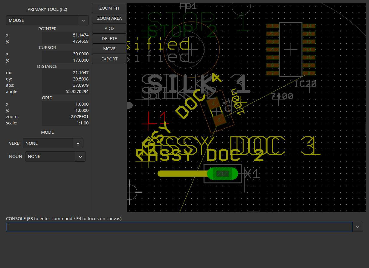
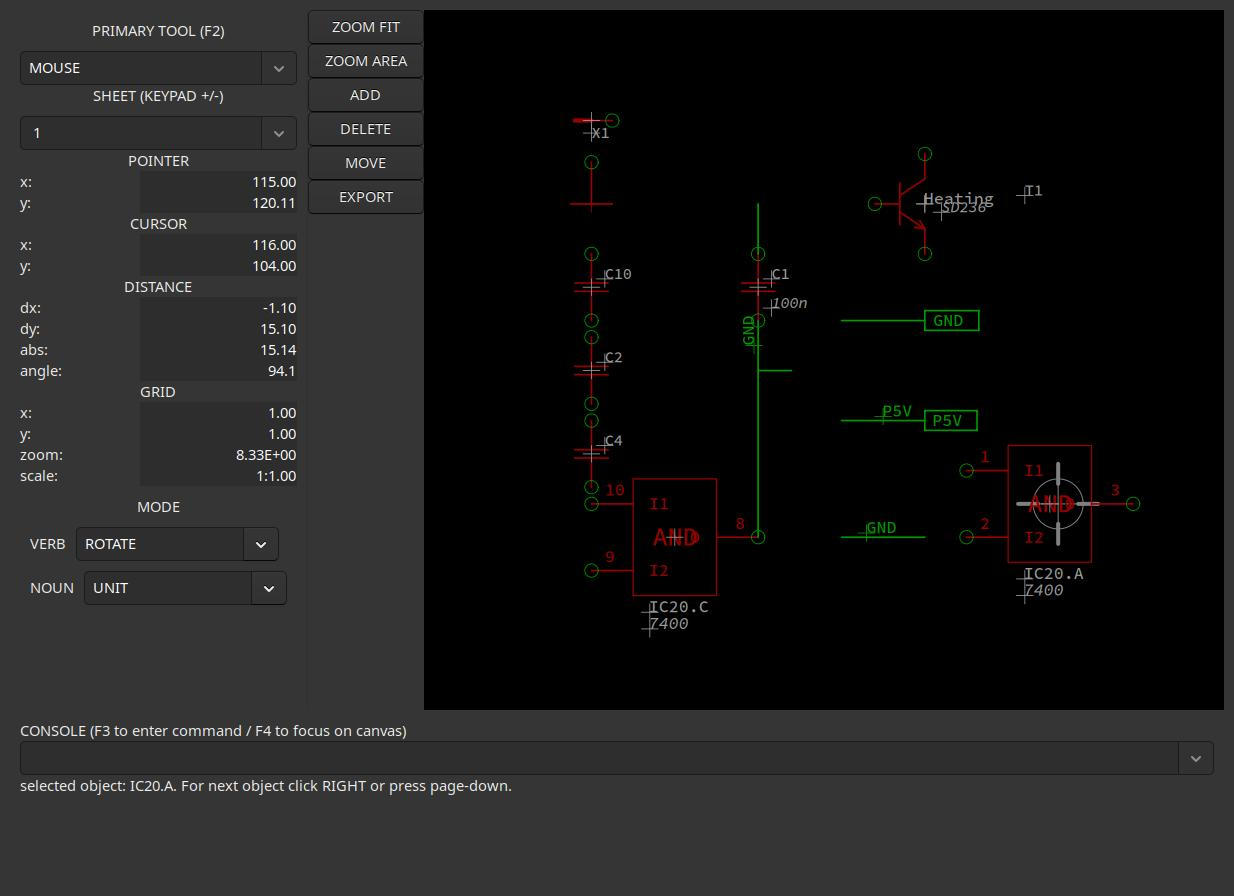
Please find two screenshots of the schematic and the board editor showing the test project. It looks fairly chaotic because it is just a test project.
Installing GtkAda and GprBuild can be troublesome. For those who do not want to compile ET, I can also provide the executable binary file (Linux only).
Hi Mario,
thanks! I’m used to doing ASIC design where I have > 120 tools (before I stopped counting!). I have to have complete config-management. So I normally install tools in something like ///
and then use Environment Modules to create Projects so I can select exactly the right configuration of tools.
I’m reading through the Money Harris MIPS book now and realise that I will probably do this by hand but at some point tools would be useful.
I decided to install kactus2 as it’s in Gentoo, not impressed with the gui. I have a zero tolerance of crap ui’s after decades of them on Linux and coming from AmigaOS prior.
Ok, I’m on chapter 4 going over hdl’s and it’s already annoyed me. First they say VHDL was “designed by committee,” the like which is attributed to Ada all the time, I don’t know if it’s true for VHDL though.
It’s like VHDL was defined by a C guy who knew a bit of Pascal but was basing it on Ada 80.
library IEEE; use IEEE.STD_LOGIC_1164.all;
Why not with and use?? What’s with the .all?? Why STD_LOGIC_1164 in all caps? Why not just IEEE.Logic_1164?
entity inv is
   port(a: in STD_LOGIC_VECTOR(3 downto 0);
        y: out STD_LOGIC_VECTOR(3 downto 0));
end;

architecture synth of inv is
begin
   y <= not a;
end;
Why downto? Why not .. ranges?
Why architecture synth? something better could be used here. I get that they’re not functions, but this is just weird.
I definitely think a new HDL based on Ada 2025 could do better here, hierarchical packages, better naming, use of ranges, use of aspects.